
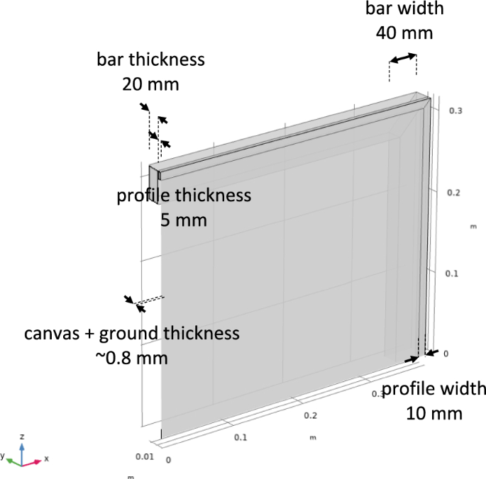
Mechanical properties
Mechanical parameters of the components building up a model painting are detailed in Table 1. The properties of oak white—one of the wood species of moderate stiffness—were assigned to the wooden bars of the stretcher [29]. A parametric study of the influence of the wood’s modulus of elasticity on the stress development in the painting was performed. Stretchers made of stiffer wood than oak white were found to reduce the maximum stresses and render their distributions more uniform. Therefore, medium-hard woods were considered to be the worst-case selection. In the analysis, the moisture-induced dimensional change of wood was neglected as the stretcher response time to RH variations is much longer than the response time of thin layers of canvas or ground which can be assumed to be instantaneous [8]. Furthermore, under desiccation, the stress in the ground and paint layers is greater when the shrinkage of the stretcher is minimal [18]. Therefore, neglecting it allowed the worst-case scenario to be considered. Finally, this study has focused on cracks induced by the moisture-related dimensional change of glue-sized canvas and the ground layer, and the inclusion of the moisture response of the wooden stretcher would mix the two mechanisms.
Tensile properties of canvases sized with animal glue were adopted from [8]. In the study, the Boltzmann sigmoid function was used to relate their nominal moduli of elasticity to RH determined at a loading of 0.2 kN/m experienced by a well-tensioned canvas painting and using the measured thicknesses of the materials. Despite the large variability of the data determined for various specimens of glue-sized canvases, reflecting the inhomogeneity of glue distribution over the canvas surface, the transition from glassy to ductile state at RH of 78% was satisfactorily described by the Boltzmann function.
Canvas or canvas-glue composites are not homogenous materials. To numerically model the canvas, Mecklenburg and Tumosa established that the mean cross-section area per yarn in the yarns separated from canvases was on average 0.22 of the nominal textile area per yarn, calculated from the measured canvas thickness [32]. The effective thickness of the ‘compact’ fibre layer in the canvases analysed in [8] was accordingly calculated from the measured textile thickness and the number of yarns on the assumption of 0.22 as the ratio between the real and nominal cross-section areas per yarn. In, turn the effective thickness of the glue layer in the sized canvases was calculated from the amount of glue and its density. Finally, the effective thickness of the sized canvas was obtained by adding the effective thicknesses of the fibre and glue layers. The parameter was determined to be only 0.21 of the measured material thickness (average for an open-weave canvas CTS2297). The effective moduli were therefore approximately 1/0.21 or 4.7 times larger than the nominal ones given in Table 1.
Moduli of elasticity of the chalk-glue ground determined from the slope of the load-extension curve in the linear region at various RH levels are presented in Fig. 3. The material’s transition from the stiff to ductile (gel-like) state is observed, a tendency well-documented in [33]. Several mathematical functions were tested and the double Boltzmann sigmoid function was fitted to the experimental data as it was found to follow accurately the transition. The parameters obtained from the fit are given in Table 1.

Elasticity moduli of chalk-glue ground versus RH with the average curve calculated from the fit of the data to the double Boltzmann function
The linear hygroscopic expansion coefficients of the glue-sized canvas and the chalk-glue ground used in the modelling are listed in Table 2. For the canvas, the coefficient perpendicular to the surface was assumed to be an average of the values in the weft and warp directions.
Outcome of the modelling
In the mechanical analysis, stress is expressed as three principal components in mutually perpendicular directions—SP1, SP2, and SP3. SP1 is the maximal stress, SP2 is the maximal stress in directions perpendicular to the SP1, and SP3 is the remaining stress perpendicular to both. In this study, stress was analysed in the middle of the thickness of the ground layer. SP2 was in the out-plane direction and was insignificant. SP1 and SP3 were the in-plane perpendicular components of the stress tensor. The simulations showed that SP1 was positive and SP3 negative, indicating tension and compression, respectively. Figure 4 shows the distribution of SP1 and SP3 induced by a drop in RH from 80 to 30%. The maximum SP1 values arose in the corners of the painting and they decreased towards the centre by a factor of approximately 13 (from 10 to 0.76 MPa). An identical stress decrease factor was obtained for an RH drop from 50 to 10%, that is, in drier conditions. The tensile stress reduction was caused by the shrinkage of the sized canvas, which in turn caused pulling inwards the supporting stretcher (Fig. 5). In consequence, the deformation of the stretcher caused compression in the ground layer instead of tension that would have occurred if the stretcher had been very stiff. The compression was particularly pronounced in the area near the middle parts of the stretcher bars where the inward deflection was the largest. The effect weakened closer to the corners as joints of the stretcher bars prevented any significant movement.

SP1 (left) and SP3 (right)—engendered in the ground layer by an RH drop from 80 to 30%—shown in a quarter of a painting with the upper right corner. The arrows indicate the directions of the respective stress components

Planar displacement in the canvas painting engendered by an RH drop from 80 to 30% (the z component of displacement was set to zero) (left); displacement of the top bar in the middle with the initial position indicated by black lines (the deformation is enlarged 2 times for the purpose of visualisation) (right)
The profile of the SP1 plot along the diagonal from the centre to the corner of the painting agrees well with the modelling results obtained by Lee et al. [18] (Fig. 6) while the stress values dramatically differ. The differences in the two studies result from using by Lee et al. mechanical parameters of paint, ground, and glue in the state of full stress relaxation, reflecting stresses in a painting induced by slow variations of environmental parameters, for example, an annual seasonal change in the environment of a painting. Canvas paintings respond in hours to humidity variations and therefore the stress relaxation would be insignificant for short-term variations. The experiments performed with mock-up paintings as well as a small historical painting showed that stress relaxation was much smaller than assumed by Lee et al. [34] and forces induced in the painting by RH variations—measured and modelled—showed a good agreement. This is a crucial issue in the reliable modelling of paintings as the force produced by the sized canvas and ground layer is the cause of the stretcher deflection.

SP1 along the diagonal from the centre to the corner of the painting obtained in this work and by Lee et al. [18], the latter data are multiplied by a factor of 40
The simulations showed that varying thickness of the ground layer—from 0.15 mm to 0.3 and 1 mm—had a significant influence on the stress levels as well as the inhomogeneity of the stress distribution but not on the tendencies in the stress distributions. In general, thicker ground layers reduce the overall shrinkage of the sized canvas and in consequence, stresses in the ground are lowered, due to the lower hygric-expansion coefficient of the ground compared to the sized canvas, the deformation of the stretcher decreases, and stress distribution is more uniform.
The plot of SP1 along the diagonal generated by the RH drop from 90 to 20% in the uncracked painting with the 0.15 mm thick ground layer is compared in Fig. 7 with the same plot for the painting in which four cracks were introduced. The maxima in the SP1 between the cracks are located approximately in the middle between cracks and they are larger than the strength of the ground at 20% RH. The strength was calculated as the product of the modulus of elasticity and the strain at break determined to be around 0.002 at RH below 50% [31].

SP1 induced along the diagonal in a canvas painting by the RH drop from 90 to 20%: no cracks (black line); four cracks separated by a distance of 10 mm (green line). The red dashed line indicates the strength of the ground at 20% RH
The relationships between SP1 normalized to the ground layer’s strength σ0 (σ0 = Eg(RH) ∙ 0.002) in the point of stress calculation and the distance between cracks S normalized to the thickness of the ground layer t, termed the S/t ratio, are shown for various RH changes and two thicknesses of the layer in Fig. 8. Using the normalized stress is a convenient way to relate stress caused by various RH changes to the material’s strength. The normalized SP1 varies slowly for the S/t ratio greater than 50 and drops suddenly for S/t smaller than 25. When the S/t ratio is smaller than 10, SP1 becomes negative, that is stresses become compressive. No new cracks nucleate in the middle of a paint island if normalized SP1 drops below 1. The critical values of S/t defined by these conditions increase for the ground layer thickness of 0.15 mm from 30 to 50 for RH changes of decreasing magnitude. For the thickness of 0.3 mm, the critical value increases to 55 for the largest RH drop considered while smaller RH drops do not induce new cracks at all. The reason for the decreased vulnerability of a canvas painting to RH variations with increasing ground layer thickness is the limitation of the hygric response of the sized canvas by thick ground.

Normalized mean SP1 engendered in the ground layer of thicknesses 0.15 mm (left) and 0.3 mm (right) by RH drops of varying magnitudes as a function of S/t
The presence of cracks decreases the vulnerability of the painting to cracking and influences the endangered area in which further cracks may be formed. Natural questions arise as to how many cracks will form, what the distances between them will be, and how the area endangered by further cracking will decrease with the increasing number of cracks formed. Since the calculation of stress fields in a cracked painting is time-consuming and increases with each added crack, methods to provide a quick estimation of crack positions were needed. One such method was to look at the stress just along the diagonal of the painting and compare the stress field in an uncracked painting to stress fields in paintings with an increasing number of cracks. The ratio of SP1 along the diagonal calculated for painting with one crack to the solution without cracks was described by a double Lorentz function with five free parameters:
$$y={y}_{0}+\frac{2{A}_{1}}{\pi }\frac{{w}_{1}}{4{\left(x-{x}_{c}\right)}^{2}+{w}_{1}^{2}}+\frac{2{A}_{2}}{\pi }\frac{{w}_{2}}{4{\left(x-{x}_{c}\right)}^{2}+{w}_{2}^{2}}$$
(1)
where xc is the distance from the painting’s corner. The double Lorentz function was chosen out of several peak functions tested as it followed most precisely the sharp fall and rise of the stress around the crack region. Parameters obtained for the ground layer thickness of 0.15 mm by fitting Eq. 1 to the data were y0 = 1.047, A1 = -0.0027, A2 = -0.034, w1 = 0.0017, w2 = 0.33. The modelling revealed that the decrease in the magnitude of the SP1 due to the presence of a crack did not significantly depend on the position of the crack. The observation made possible a simple procedure of calculating variations of SP1 along the diagonal on sequential addition of cracks, termed from here the sequential addition procedure, illustrated in Fig. 9. The first crack was located at the point of the highest stress at the distance xc of 28 mm and the corresponding variation of SP1 was calculated using the function derived. The next crack was located at xc of 0.014, selected as the least distance of the first crack to the corner in the practical model of a canvas painting developed. SP1 variations along the diagonal were again calculated. The next crack towards the painting’s centre was added at the point of the highest stress at xc of 0.039. Further cracks can be located towards the painting’s centre using the procedure.

Plots of SP1 induced along the diagonal in a canvas painting with an increasing number of cracks by the RH drop from 90 to 20%: no cracks (black line), one crack (left), two cracks (middle), and three cracks (right). The red dashed line indicates the strength of the ground at 20% RH. SP1 variations calculated with the use of the sequential addition procedure (solid lines) are compared to the outcome of the full simulation (dashed lines)
The sequential addition procedure proved very useful in identifying points of the highest stress along the diagonal and locating in them subsequent cracks in the ground layer. As illustrated in Fig. 9, the SP1 variations calculated using the sequential addition procedure agree well with the outcome of the full simulation. However, the procedure is approximate, and performing the full simulation of stress distributions might be needed for the approximate set of cracks established. Figures 10 and 11 illustrate the issue. The SP1 changes along the diagonal of a painting calculated by locating eleven cracks with the use of the sequential addition procedure are compared with full simulations involving the same cracks in Fig. 10. Although the approximate procedure indicated that the stress in the entire cracked area dropped below the strength of the material and the saturation of the crack patterns occurred, the full simulation indicated stress magnitude exceeding the strength at distances of 25, 52, 60, 68, and 79 mm from the corner. Only when further four cracks had been introduced at distances of 25, 52, 60, and 79 mm, the stress reduction below the critical level was achieved (Fig. 11).

Plots of SP1 induced along the diagonal in a canvas painting with 11 cracks by the RH drop from 90 to 20%, no cracks (black line). The red dashed line indicates the strength of the ground layer at 20% RH. SP1 variations calculated with the use of the sequential addition procedure (solid lines) are compared to the outcome of the full simulation (dashed lines)

Plots of SP1 induced along the diagonal in a canvas painting with 15 cracks by the RH drop from 90 to 20%, calculated using the full simulation, no cracks (black line). Additional four cracks were added to 11 cracks illustrated in Fig, 10 at distances of 25, 52, 60, and 79 mm from the corner. The red dashed line indicates the strength of the ground layer at 20% RH
By way of example, the modelling was applied to the analysis of cracks in a corner of an experimental mock-up painting constructed with a stretched canvas, a hide glue size, and a stiff glue-based ground acting as a design layer and subjected to cycles of large changes in RH (Fig. 43 in [24]). It was reported in the study that additional cycling beyond the initial nine cycles did no further damage as the cracks that occurred relieved the stresses.
Approximately 9 cracks are visible in the corner shown in Fig. 12 with an average spacing of about 6 mm and a standard deviation of 3 mm. It is expected that the crack spacing should increase with increasing distance from the corner, however, this effect is not evident in this case. It was assumed that the model canvas painting investigated in this study represented adequately the mock-up painting analysed. The sequential addition procedure and the full simulation of 11 or 15 cracks introduced (Figs. 10 and 11) yielded the predicted distance between cracks of 6 ± 2 mm and 5 ± 2 mm, respectively, which agrees very well with the observed one. The predicted cracked area (distances along the diagonal of 72 or 79 mm to the corner) is larger than the observed one but, in general, reflects the overall risk of cracking. There are several sources of uncertainty in the predictions but the most significant lies in the assumption that the stress-free state corresponds to the highest RH level, 90% in the modelling. If the stress-free state in the real painting corresponded to a lower RH level, the model prediction would overestimate the size of the cracked area and underestimate the distance between cracks.

Mock-up painting with cracks induced by several RH cycles between 95 and 20%. The red line indicates the predicted distance between cracks obtained with the use of the sequential addition procedure and the dashed line indicates the size of the cracked area